


1) It is best to use natural cooling for most small electronic components.
2) Make maximum use of simple and reliable cooling technologies such as heat conduction, natural convection and radiation.
3) Shorten the heat transfer path of the heat sink as much as possible and increase the heat exchange or heat conduction area.
4) The heat generated in the module should be dissipated through the module chassis and mounting frame as much as possible.
5) Reduce the contact thermal resistance of the heat sink during installation, and the arrangement of components is conducive to the convective heat transfer of the fluid.
6) Adopt heat dissipation circuit board, edge guide rail with low thermal resistance.
7) The installation direction and installation method of the components should ensure the maximum use of convection to transfer heat. The installation method of components should fully consider the influence of heat radiation from surrounding components, etc., to ensure that the temperature of each component does not exceed its maximum operating temperature, and should avoid exceeding hot spots.
8) The distance between circuit board components is controlled at 19-21mm, and there should be no interference between components, sockets and heads on adjacent boards in a vibrating environment.
9) Thermal isolation measures should be taken for heat-sensitive components close to the heat source; Increase the blackness of the surface of the chassis and enhance the radiation heat transfer of the heat sink.
10) The key to the natural cooling design of the transformer is how to reduce the thermal resistance of the heat transfer path. A thicker wire should be used and good thermal contact should be made between it and the mounting structure. The installation surface should be flat and smooth. Metal foil can be added to the contact interface to reduce the interface thermal resistance. If the transformer has a shielding cover, it should be possible to make a good thermal connection between the shielding cover and the base. Putting a copper tape between the shell or core and the base helps to enhance the guiding ability.

Natural cooling and heat dissipation technology process selection:
profile heat dissipation: aluminum profile heat sink, aluminum alloy heat sink, copper and aluminum composite heat sink
Profile splicing: friction welding heat sink, stacked heat sink, insert heat sink
skiing fins technology: aluminum skiing fins heat sink, copper skiing fins heat sink
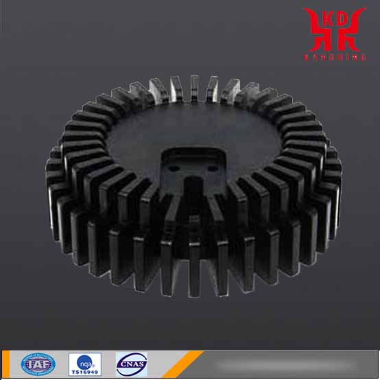
Forging technology: cold forging heat sink, sun flower heat sink
Machining technology: turning and milling aluminum heat sink, turning and milling copper heat sink
Die-casting technology: die-cast heat sink, cast heat sink

The cooling scheme of LED natural cooling:
Schematic diagram and parameters of the simulation model:
Ambient temperature: 25℃,
Chip heat consumption: 24W,
Heat sink: black anode on the surface,
Emissivity: 0.85.
Schematic diagram of vertical simulation results:
Cross-sectional temperature distribution diagram at the center of the model
Vertical heat sink temperature distribution diagram
(Ambient temperature: 25°C. Chip heat consumption: 24W, maximum temperature of heat sink 63.92°C)
Schematic diagram of horizontal simulation results:
Distribution of velocity at the center section of the model
Distribution diagram of the temperature of the radiator in the horizontal direction
Distribution map of horizontal flow trace
Summary of simulation results of LED heat dissipation:
| H.S plan | Placement direction | Ambient temperature | Heat sink emissivity | Heat consumption | Maximum temperature of heat sink |
| Aluminum extrusion radiator | Upright | 25℃ | 0.85 | 25W | 63.92℃ |
| Level | 71.2℃ |