

High-power, high-brightness light-emitting diodes (LEDs) are now gradually entering many lighting applications due to their good color saturation and long life. However, how to avoid overheating of LEDs is a major test that thermal design engineers must face. Therefore, in the design process, the importance of ComputaTIonal Fluid Dynamic (CFD) model has become more and more prominent. In this article, we will compare the experimental results of high-power LEDs with star-shaped metal core printed circuit boards (MCPCB), packaged with and without heat sink. After the comparison and discussion, we will provide a temperature model building technology applied to LED packages with heat sinks. From this point of view, the results obtained by using the CFD model are quite feasible, and it also shows that this technology can be applied to the evaluation of the LED system level. The article will discuss the effects of using thermal interface material (TIM) on LED packaging.
Estimate LED heat dissipation and simplify product design
Being able to estimate the heat dissipation performance of LEDs in advance is a fact that cannot be ignored for assisting design engineers to effectively shorten the time to market for LED products. However, when the heat flow and packaging density become higher, the heat dissipation design of the LED package module becomes more difficult, and the module design and thermal energy analysis are also more important. Therefore, CFD simulation has become a commonly used method for thermal energy analysis in the initial design of electronic products. CFD mainly includes numerical simulation analysis of fluid flow, heat conduction and heat radiation and other related programs.
This article proposes the steps to build a high-power LED star package with a heat sink. First, a detailed model is established for the LED package using a star-shaped substrate, and then a heat sink is added to the bottom of the LED star-shaped package, and finally the simulation results are compared with the experimental data.
Another key point of the article is the impact of TIM on LED packaging. The main purpose is to find out the characteristics of different interface thickness (Bond Line Thickness, BLT) heat dissipation interface materials and the percentage of voids in the material.
Build technology based on temperature model
The LED package with a star-shaped substrate is modeled using the CFD tool Flotherm produced by Flomeric.
Model description is the first task
First, establish a detailed model to find out the error percentage between the actual measurement results. Refer to Table 1 for the detailed size parameters of the LED package and the thermal conductivity of the packaging material.

Table 1 The structure details of the LED star-shaped package with heat sink and the thermal conductivity of the packaging material
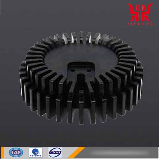
Figure 1 shows the front view and layout of the LED package. Add solder paste between the package and the substrate. When the package reaches the maximum power of 1.3 watts, standard natural and forced convection air heat dissipation methods are used, and the contact surface temperature cannot be maintained within the acceptable range below 125°C. Therefore, a heat sink must be added to meet the target temperature requirements, and the heat sink must be packaged on the LED. First, paste the thermal tape on the back end of the heat sink, and then package the heat sink on the bottom of the LED substrate.

Fig. 1 The picture above shows the front and side views of Avago Technologies’ Moonstone star-packed power LED ASMT-Mx09. The picture below shows the LED product ASMT-Mx09 in star packaging.
Set grid/boundary conditions again
To perform CFD analysis, it is necessary to assume three-dimensional space, steady state, stable airflow, stable air characteristics, ambient temperature of 25°C, and calculation range of 305 mm & TImes;
305 mm × 305 mm, and the heat dissipation method through natural heat dissipation, heat conduction and heat radiation conditions.
The overall grid number of the base LED package of the detailed heat sink model is about 200,000. In the grid number setting, it is recommended to use at least three between each fin of the heat sink.
Analysis of thermal resistance / numerical values / experimental results
Next, we need to calculate the thermal resistance, numerical analysis and experimental results.